Dual Power Feed Installation for Dashcam Hardwire in Nissan Almera
Article Date: 09/11/19
A short while ago, I wrote an article on fitting a hardwiring kit to my car for my dashcam when I'm driving. This prevents draining the battery when I'm parked up, and generally only records the car when you're driving. It causes a problem however, when I'm going shopping, I wanted my car to have the ability to record the car when parked up to protect it against accidents when shopping.
There are already methods on the market for this (usually £200 LiPo battery packs), however I wanted something simple. So here's my simple solution to the problem that I thought up and used. I prefer the K.I.S.S (Keep It Simple Stupid) principle. No point complicating things here. Only one power configuration is ever powered at the same time because of the ON/OFF/ON switch design. The central switching deactivates one and engages the other
Has it worked? - Yes - total cost about £5
DISCLAIMER:
Before I go ahead with this guide, I'm not an Automotive Electrician, so do this at your own risk. This is my approach, and it works for me. If your car catches fire. That's your issue, not mine. I'm confident in my own abilities enough to do this installation.
WHAT'S NEEDED? (To hardwire your dashcam with two power feeds)
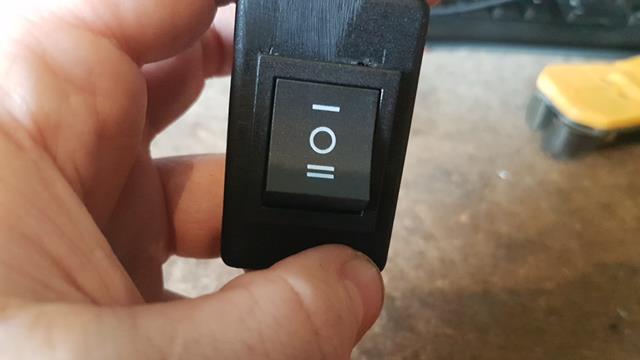
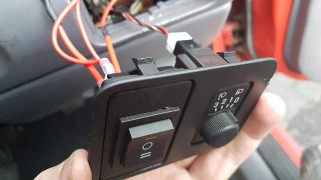
Double Pole - Double Throw Switch (Either ON/ON type or ON/OFF/ON type) - I chose the ON/OFF/ON type, so I could completely switch my camera off by leaving the power switch in the central position, plus it helps remind me what position I'm connecting it to the secondary feed
HOW DOES IT WORK?
A double pole switch, can accept TWO inputs.
- One input is wired (via a piggy back fuse) to a +12V Switch Live Feed.
- One input is wired (via a piggy back fuse) to a +12V Permanent Live Feed.
The switch then accepts two outputs.
- Position 1 - When used, is the switched live feed, flick the switch to this, and your car only powers the dashcam when keys in car and driving
- Position 2 - When used, switches the power output to the permanent feed, need to go shopping. Worried about car park dingers. Flick the switch
HOW IS THE CAMERA POWERED?
Same procedures as the original fitting kit, just each individual output on the DPDT switch is joined as one. Two outputs --> One input
Think of the output terminals like headphones. Position 1 is the Left Ear, Position 2 is the Right Ear. The cables then join together like headphones, and where they join is a bullet connector. This is the power source for the normal dashcam hardwire kit. Then just wire the dashcam kit to earth
Being a DPDT switch, I've actually got 2 more spare outputs I could use for something else in the car. They're just left alone for now though. I have no need for them. can now be safe in the knowledge that I have a Dashcam for everyday driving in the car, and when I want to do a shopping trip, I just flick the switch and then let it run
MATERIALS NEEDED TO DUAL FEED THE DASHCAM
- DPDT Switch (On-Off-On) Configuration (Just search for "DPDT On-Off-On" on sites like ebay - Mine cost £1.89
- Two Piggy Back Fuse Kits
- 5-Amp Cable, connectors and heatshrink to extend wires as necessary
NEED A GUIDE ON HOW TO CREATE IT YOURSELF?
At this moment in time I no longer produce PDF guides for download from my site. It's faster loading the pictures inline via my webserver and it was causing a high bounce rate on my website as people were going straight to the articles and leaving. I'm attempting to increase user navigation on the site. If you really really want a PDF version of the below, you can purchase it from my store. They're nice and cheap as I know the guides are basic. They are nothing more than .PDF versions of these documents. Purchasing them simply helps support my website and writing articles. By purchasing them however, you only have permission to use the document for personal use. You have NO permission to share/resell my document
ON WITH THE FITTING...
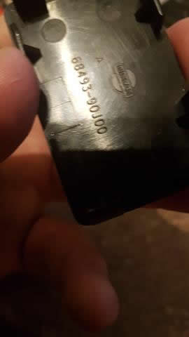
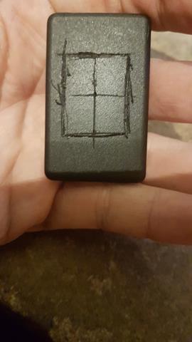
First remove the blanking plate from the car. For reference if you don't want to butcher yours (or keep the original), the original OEM part number for the blanking plate is 6849390J00. You remove it from the car by using a flat-bladed screwdriver or non-marring plastic spudger around the edges. Once you have removed it, score the template of where you need the switch to be installed. Measure the back of the switch (width and height) and then transfer these measurements to the template. As you can see there is very little room to play with. I wanted it as close as centre as possible so I measured the width and the height of the blanking plate too so I could find the centre point
You will then have to cut out the excess plastic to fit the switch. I originally started using a file but it took forever. So I ended up melting the plastic using a soldering iron and then filing it down with the file. Way faster. This is when I first test-fitted it into the unit. Pretty close indeed
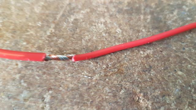
The next step was the wires. I test fitted them to the car, however they're a little short (they could probably "just" fit), but I didn't like that. So I modified them. I wanted a bit of headroom to play with. Wires were soldered for strength
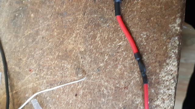
KISS principle, but always remember to protect them with heatshrink to prevent short-circuits
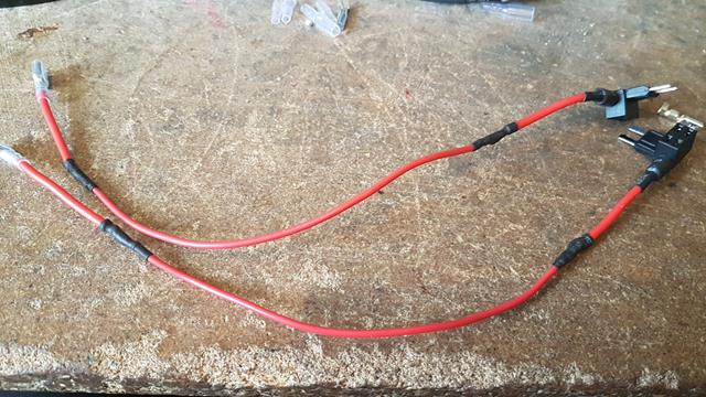
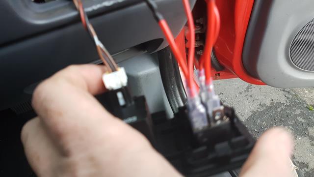
The finished modified piggy back fuses. After I finished soldering I tested for continuity in the wires to make sure they had a good connection. For information, if you want to test this. You will need to install 2 fuses, as the circuit carries through the piggy back. You then measure prongs to connector. Mine were good, as you can see they're a good 6" longer now, plenty of room
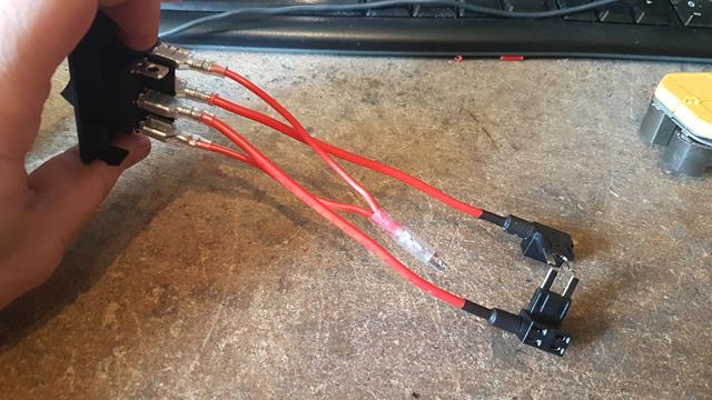
The finished kit, simple as it will be installed in the car (this picture was taken before I lengthened the wires). If you need more help understanding this see below. If there's enough interest, I may consider selling these direct kits in my store too
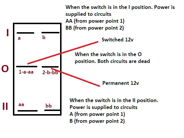
As you can see in the picture above, this is how the kit is wired up. It's done this way, so that only power is taken from one circuit at a time. Both power outputs are joined into one connector so that each one outputs power when switched on. It saves on the wiring
- Switched Live Fuse, is attached to point (1-a-aa), the output power goes from point aa
- Permanent Live Fuse, is attached to point (2-b-bb), the output power goes from point b
- Power is taken from points b/aa and then joined up into a bullet connector. This acts as the "12v" feed for the dashcam hardwire
I then pushed the blanking plate back into it's position
The rear connectors of the DPDT switch
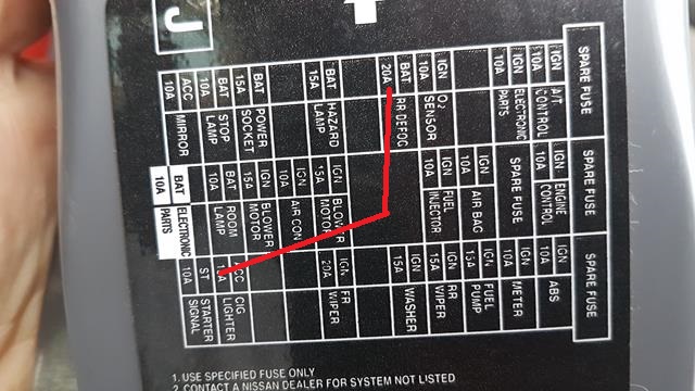
These are the circuits that I tapped on my Almera for the DPDT switch. I tried to select circuits that were "non-critical", so that if something went wrong and I lost them. It wouldn't affect me driving the car. Most cars have a picture, the Almera has an arrow that designates the direction of the fuses. I tapped into the following two circuits (Permanent 12V = Rear Defog Circuit), (Switched 12V = Cigarette Lighter Circuit).
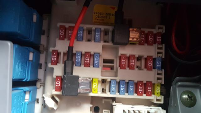
A picture of the two circuits I tapped into for reference. The top one is the Perm-Live 12v, the bottom one is the original installation point
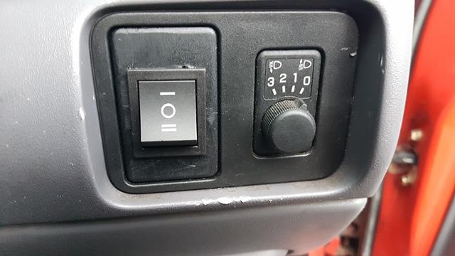
The finished installation in my car. Mounted next to the headlamp adjustment switch. It doesn't bother me what it looks like. I just thought it would be always useful to have the switch installed at this point as it has no other use, other than a blanking plate for another circuit
ET VOILA! - That's how you have a hardwired dashcam into the car with Dual Power Feeds. I use position 1 for driving, and position 2 for parking